Think you know how routers work? These devices use intricate formulas to figure out exactly where to send a packet and how to get it there. See more computer networking pictures.
If you have read the HowStuffWorks article How Routers Work, then you know that a router is used to manage network traffic and find the best route for sending packets. But have you ever thought about how routers do this? Routers need to have some information about network status in order to make decisions regarding how and where to send packets. But how do they gather this information?
In this article, we'll find out precisely what information is used by routers in determining where to send a packet.
Routers use routing algorithms to find the best route to a destination. When we say "best route," we consider parameters like the number of hops (the trip a packet takes from one router or intermediate point to another in the network), time delay and communication cost of packet transmission.
Based on how routers gather information about the structure of a network and their analysis of information to specify the best route, we have two major routing algorithms: global routing algorithms and decentralized routing algorithms. In decentralized routing algorithms, each router has information about the routers it is directly connected to -- it doesn't know about every router in the network. These algorithms are also known as DV (distance vector) algorithms. In global routing algorithms, every router has complete information about all other routers in the network and the traffic status of the network. These algorithms are also known as LS (link state) algorithms. We'll discuss LS algorithms in the next section.
Advertisement
LS Algorithms
In LS algorithms, every router has to follow these steps:
Identify the routers that are physically connected to them and get their IP addresses When a router starts working, it first sends a "HELLO" packet over network. Each router that receives this packet replies with a message that contains its IP address.
Measure the delay time (or any other important parameters of the network, such as average traffic) for neighbor routers In order to do that, routers send echo packets over the network. Every router that receives these packets replies with an echo reply packet. By dividing round trip time by 2, routers can count the delay time. (Round trip time is a measure of the current delay on a network, found by timing a packet bounced off some remote host.) Note that this time includes both transmission and processing times -- the time it takes the packets to reach the destination and the time it takes the receiver to process it and reply.
Broadcast its information over the network for other routers and receive the other routers' information In this step, all routers share their knowledge and broadcast their information to each other. In this way, every router can know the structure and status of the network.
Using an appropriate algorithm, identify the best route between two nodes of the network In this step, routers choose the best route to every node. They do this using an algorithm, such as the Dijkstra shortest path algorithm. In this algorithm, a router, based on information that has been collected from other routers, builds a graph of the network. This graph shows the location of routers in the network and their links to each other. Every link is labeled with a number called the weight or cost. This number is a function of delay time, average traffic, and sometimes simply the number of hops between nodes. For example, if there are two links between a node and a destination, the router chooses the link with the lowest weight.
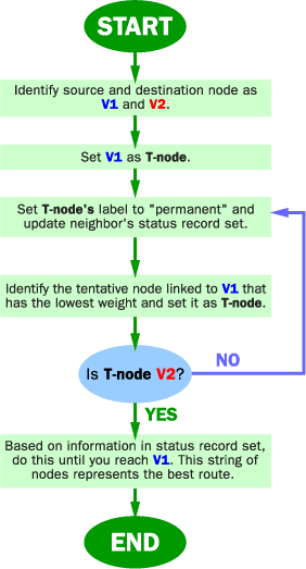
The Dijkstra algorithm goes through these steps:
Advertisement
The router builds a graph of the network and identifies source and destination nodes, as V1 and V2 for example. Then it builds a matrix, called the "adjacency matrix." In this matrix, a coordinate indicates weight. For example, [i, j] is the weight of a link between Vi and Vj. If there is no direct link between Vi and Vj, this weight is identified as "infinity."
The router builds a status record set for every node on the network. The record contains three fields: Predecessor field - The first field shows the previous node. Length field - The second field shows the sum of the weights from the source to that node. Label field - The last field shows the status of node. Each node can have one status mode: "permanent" or "tentative."
The router initializes the parameters of the status record set (for all nodes) and sets their length to "infinity" and their label to "tentative."
The router sets a T-node. For example, if V1 is to be the source T-node, the router changes V1's label to "permanent." When a label changes to "permanent," it never changes again. A T-node is an agent and nothing more.
The router updates the status record set for all tentative nodes that are directly linked to the source T-node.
The router looks at all of the tentative nodes and chooses the one whose weight to V1 is lowest. That node is then the destination T-node.
If this node is not V2 (the intended destination), the router goes back to step 5.
If this node is V2, the router extracts its previous node from the status record set and does this until it arrives at V1. This list of nodes shows the best route from V1 to V2.
We will use this algorithm as an example on the next page.
Advertisement
Example: Dijkstra Algorithm
Step 1
Step 2
Step 3
Step 4
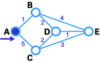
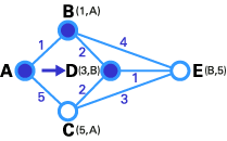
Here we want to find the best route between A and E (see below). You can see that there are six possible routes between A and E (ABE, ACE, ABDE, ACDE, ABDCE, ACDBE), and it's obvious that ABDE is the best route because its weight is the lowest. But life is not always so easy, and there are some complicated cases in which we have to use algorithms to find the best route.
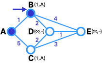
As you see in the first image, the source node (A) has been chosen as T-node, and so its label is permanent (we show permanent nodes with filled circles and T-nodes with the --> symbol).
In the next step, you see that the status record set of tentative nodes directly linked to T-node (B, C) has been changed. Also, since B has less weight, it has been chosen as T-node and its label has changed to permanent (see below).
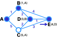
In step 3, like in step 2, the status record set of tentative nodes that have a direct link to T-node (D, E), has been changed. Also, since D has less weight, it has been chosen as T-node and its label has changed to permanent.
In step 4, we don't have any tentative nodes, so we just identify the next T-node. Since E has the least weight, it has been chosen as T-node.
Lastly, E is the destination, so we stop here.
Advertisement
We are at end! Now we have to identify the route. The previous node of E is D, and the previous node of D is B, and B's previous node is A. So the best route is ABDE. In this case, the total weigh is 4 (1+2+1).
Although this algorithm works well, it's so complicated that it may take a long time for routers to process it, and the efficiency of the network fails. Also, if a router gives the wrong information to other routers, all routing decisions will be ineffective. To understand this algorithm better, here is the source of program written by C:
#define MAX_NODES 1024        /* maximum number of nodes */
#define INFINITY 1000000000      /* a number larger than every maximum path */
int n,dist[MAX_NODES][MAX_NODES];  /*dist[I][j] is the distance from i to j */
void shortest_path(int s,int t,int path[ ])
{struct state {                          /* the path being worked on */
int predecessor ;                     /*previous node */
int length                                /*length from source to this node*/
enum {permanent, tentative} label    /*label state*/
}state[MAX_NODES];
int I, k, min;
struct state *
                     p;
for (p=&state[0];p < &state[n];p++){       /*initialize state*/
p->predecessor=-1
p->length=INFINITY
p->label=tentative;
}
state[t].length=0; state[t].label=permanent ;
k=t ;
/*k is the initial working node */
do{
/* is  the better path from k? */
for I=0; I < n; I++)
/*this graph has n nodes */
if (dist[k][I] !=0 && state[I].label==tentative){
            if (state[k].length+dist[k][I] < state[I].length){
		       state[I].predecessor=k;
		       state[I].length=state[k].length + dist[k][I]
		    }
}
/* Find the tentatively labeled node with the smallest label. */
k=0;min=INFINITY;
for (I=0;I < n;I++)
     if(state[I].label==tentative && state[I].length <
min)=state[I].length;
     k=I;
	}
state[k].label=permanent
}while (k!=s);
/*Copy the path into output array*/
I=0;k=0
Do{path[I++]=k;k=state[k].predecessor;} while (k > =0);
}
Advertisement
DV Algorithms
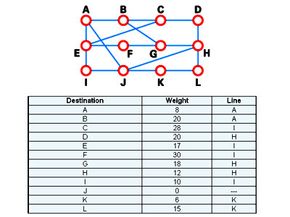
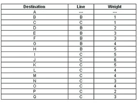
A typical network graph and routing table for router J
HowStuffWorks.com
DV algorithms are also known as Bellman-Ford routing algorithms and Ford-Fulkerson routing algorithms. In these algorithms, every router has a routing table that shows it the best route for any destination. A typical graph and routing table for router J is shown at the top of the page.
As the table shows, if router J wants to get packets to router D, it should send them to router H. When packets arrive at router H, it checks its own table and decides how to send the packets to D.
Advertisement
In DV algorithms, each router has to follow these steps:
It counts the weight of the links directly connected to it and saves the information to its table.
In a specific period of time, it send its table to its neighbor routers (not to all routers) and receive the routing table of each of its neighbors.
Based on the information in its neighbors' routing tables, it updates its own.
One of the most important problems with DV algorithms is called "count to infinity." Let's examine this problem with an example:
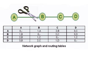
Imagine a network with a graph as shown below. As you see in this graph, there is only one link between A and the other parts of the network. Here you can see the graph and routing table of all nodes:
Network graph and routing tables
HowStuffWorks.com
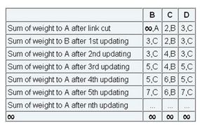
Now imagine that the link between A and B is cut. At this time, B corrects its table. After a specific amount of time, routers exchange their tables, and so B receives C's routing table. Since C doesn't know what has happened to the link between A and B, it says that it has a link to A with the weight of 2 (1 for C to B, and 1 for B to A -- it doesn't know B has no link to A). B receives this table and thinks there is a separate link between C and A, so it corrects its table and changes infinity to 3 (1 for B to C, and 2 for C to A, as C said). Once again, routers exchange their tables. When C receives B's routing table, it sees that B has changed the weight of its link to A from 1 to 3, so C updates its table and changes the weight of the link to A to 4 (1 for C to B, and 3 for B to A, as B said).
This process loops until all nodes find out that the weight of link to A is infinity. This situation is shown in the table below. In this way, experts say DV algorithms have a slow convergence rate.
The "count to infinity" problem
HowStuffWorks.com
One way to solve this problem is for routers to send information only to the neighbors that are not exclusive links to the destination. For example, in this case, C shouldn't send any information to B about A, because B is the only way to A.
Advertisement
Hierarchical Routing
Network graph and A's routing table
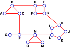
As you see, in both LS and DV algorithms, every router has to save some information about other routers. When the network size grows, the number of routers in the network increases. Consequently, the size of routing tables increases, as well, and routers can't handle network traffic as efficiently. We use hierarchical routing to overcome this problem. Let's examine this subject with an example:
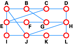
We use DV algorithms to find best routes between nodes. In the situation depicted below, every node of the network has to save a routing table with 17 records. Here is a typical graph and routing table for A:
Advertisement
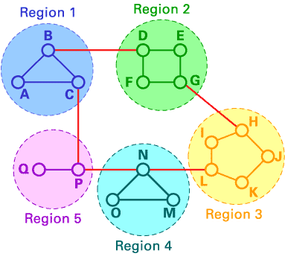
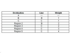
In hierarchical routing, routers are classified in groups known as regions. Each router has only the information about the routers in its own region and has no information about routers in other regions. So routers just save one record in their table for every other region. In this example, we have classified our network into five regions (see below).
If A wants to send packets to any router in region 2 (D, E, F or G), it sends them to B, and so on. As you can see, in this type of routing, the tables can be summarized, so network efficiency improves. The above example shows two-level hierarchical routing. We can also use three- or four-level hierarchical routing.
In three-level hierarchical routing, the network is classified into a number of clusters. Each cluster is made up of a number of regions, and each region contains a number or routers. Hierarchical routing is widely used in Internet routing and makes use of several routing protocols.
For more information on routing and related topics, check out the links on the next page.
Advertisement
Frequently Answered Questions
Why do we use routing algorithm?
There are several reasons why routing algorithms are used, including to find the shortest path between two nodes in a network, to avoid congestion, and to balance traffic loads.
Roozbeh Razavi is a student of electronic engineering at K.N.T University of Technology. He is also a translator of the book "Networking Essentials Plus," by Microsoft Corporation. His studies have focused on areas of TCP/IP, routing and network security.
Cite This!
Please copy/paste the following text to properly cite this HowStuffWorks.com article: