Parallel Port Basics
Parallel ports were originally developed by IBM as a way to connect a printer to your PC. When IBM was in the process of designing the PC, the company wanted the computer to work with printers offered by Centronics, a top printer manufacturer at the time. IBM decided not to use the same port interface on the computer that Centronics used on the printer.
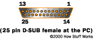
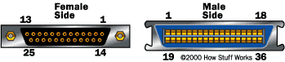
Instead, IBM engineers coupled a 25-pin connector, DB-25, with a 36-pin Centronics connector to create a special cable to connect the printer to the computer. After IBM launched its PC in 1981, other printer manufacturers ended up adopting the Centronics interface, making this strange hybrid cable an unlikely de facto standard.
Advertisement
When a PC sends data to a printer or other device using a parallel port, it sends 8 bits of data (1 byte) at a time. These 8 bits are transmitted parallel to each other, as opposed to the same eight bits being transmitted serially (in a single stream) through a serial port. The standard parallel port is capable of sending 150 kilobytes of data per second.
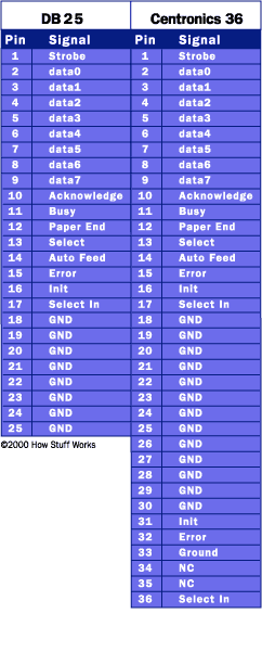
Let's take a closer look at what each pin does when used with a printer:
- Pin 1 carries the strobe signal. It maintains a level of between 2.8 and 5 volts, but drops below 0.5 volts whenever the computer sends a byte of data. This drop in voltage tells the printer that data is being sent.
- Pins 2 through 9 are used to carry data. To indicate that a bit has a value of 1, a charge of 5 volts is sent through the correct pin. No charge on a pin indicates a value of 0. This is a simple but highly effective way to transmit digital information over an analog cable in real-time.
- Pin 10 sends the acknowledge signal from the printer to the computer. Like Pin 1, it maintains a charge and drops the voltage below 0.5 volts to let the computer know that the data was received.
- If the printer is busy, it will charge Pin 11. Then, it will drop the voltage below 0.5 volts to let the computer know it is ready to receive more data.
- The printer lets the computer know if it is out of paper by sending a charge on Pin 12.
- As long as the computer is receiving a charge on Pin 13, it knows that the device is online.
- The computer sends an auto feed signal to the printer through Pin 14 using a 5-volt charge.
- If the printer has any problems, it drops the voltage to less than 0.5 volts on Pin 15 to let the computer know that there is an error.
- Whenever a new print job is ready, the computer drops the charge on Pin 16 to initialize the printer.
- Pin 17 is used by the computer to remotely take the printer offline. This is accomplished by sending a charge to the printer and maintaining it as long as you want the printer offline.
- Pins 18-25 are grounds and are used as a reference signal for the low (below 0.5 volts) charge.