How LAN Switches Work

By: Jeff Tyson
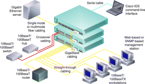
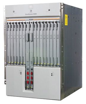
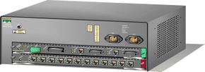
Illustration of a Cisco Catalyst switch. 

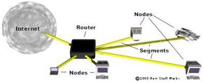
If you have read other HowStuffWorks articles on networking or the Internet, then you know that a typical network consists of:

  • nodes (computers)
  • a connecting medium (wired or wireless)
  • specialized network equipment like routers or hubs.

In the case of the Internet, all of these pieces work together to allow your computer to send information to another computer that could be on the other side of the world!

Advertisement

­Switches are another fundamental part of many networks because they speed things up. Switches allow different nodes (a network connection point, typically a computer) of a network to communicate directly with one another in a smooth and efficient manner.

­There are many different types of switches and networks. Switches that provide a separate connection for each node in a company's internal network are called LAN switches. Essentially, a LAN switch creates a series of instant networks that contain only the two devices communicating with each other at that particular moment. In this article, we will focus on Ethernet networks that use LAN switches. You will learn what a LAN switch is and how transparent bridging works, as well as about VLANs, trunking and spanning trees.


Networking Basics

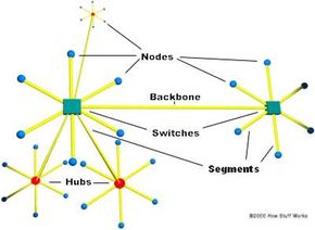
Here are some of the fundamental parts of a network:

  • Network - A network is a group of computers connected together in a way that allows information to be exchanged between the computers.
  • Node - A node is anything that is connected to the network. While a node is typically a computer, it can also be something like a printer or CD-ROM tower.
  • Segment - A segment is any portion of a network that is separated, by a switch, bridge or router, from other parts of the network.
  • Backbone - The backbone is the main cabling of a network that all of the segments connect to. Typically, the backbone is capable of carrying more information than the individual segments. For example, each segment may have a transfer rate of 10 Mbps (megabits per second), while the backbone may operate at 100 Mbps.
  • Topology - Topology is the way that each node is physically connected to the network (more on this in the next section).
  • Local Area Network (LAN) - A LAN is a network of computers that are in the same general physical location, usually within a building or a campus. If the computers are far apart (such as across town or in different cities), then a Wide Area Network (WAN) is typically used.
  • Network Interface Card (NIC) - Every computer (and most other devices) is connected to a network through an NIC. In most desktop computers, this is an Ethernet card (normally 10 or 100 Mbps) that is plugged into a slot on the computer's motherboard.
  • Media Access Control (MAC) address - This is the physical address of any device -- such as the NIC in a computer -- on the network. The MAC address, which is made up of two equal parts, is 6 bytes long. The first 3 bytes identify the company that made the NIC. The second 3 bytes are the serial number of the NIC itself.
  • Unicast - A unicast is a transmission from one node addressed specifically to another node.
  • Multicast - In a multicast, a node sends a packet addressed to a special group address. Devices that are interested in this group register to receive packets addressed to the group. An example might be a Cisco router sending out an update to all of the other Cisco routers.
  • Broadcast - In a broadcast, a node sends out a packet that is intended for transmission to all other nodes on the network.

On the next page, we'll discuss some of the most common network topologies.

Advertisement

Network Topologies

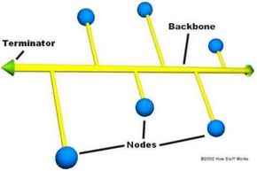
Bus network topology

Some of the most common topologies in use today include:

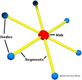
Star network topology
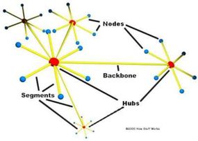
A typical star bus network
  • Bus - Each node is daisy-chained (connected one right after the other) along the same backbone, similar to Christmas lights. Information sent from a node travels along the backbone until it reaches its destination node. Each end of a bus network must be terminated with a resistor to keep the signal that is sent by a node across the network from bouncing back when it reaches the end of the cable.
  • Ring - Like a bus network, rings have the nodes daisy-chained. The difference is that the end of the network comes back around to the first node, creating a complete circuit. In a ring network, each node takes a turn sending and receiving information through the use of a token. The token, along with any data, is sent from the first node to the second node, which extracts the data addressed to it and adds any data it wishes to send. Then, the second node passes the token and data to the third node, and so on until it comes back around to the first node again. Only the node with the token is allowed to send data. All other nodes must wait for the token to come to them.
  • Star - In a star network, each node is connected to a central device called a hub. The hub takes a signal that comes from any node and passes it along to all the other nodes in the network. A hub does not perform any type of filtering or routing of the data. It is simply a junction that joins all the different nodes together.
  • Star bus - Probably the most common network topology in use today, star bus combines elements of the star and bus topologies to create a versatile network environment. Nodes in particular areas are connected to hubs (creating stars), and the hubs are connected together along the network backbone (like a bus network). Quite often, stars are nested within stars, as seen in the example below:

Advertisement

The Problem: Traffic

In the most basic type of network found today, nodes are simply connected together using hubs. As a network grows, there are some potential problems with this configuration:

  • Scalability - In a hub network, limited shared bandwidth makes it difficult to accommodate significant growth without sacrificing performance. Applications today need more bandwidth than ever before. Quite often, the entire network must be redesigned periodically to accommodate growth.
  • Latency - This is the amount of time that it takes a packet to get to its destination. Since each node in a hub-based network has to wait for an opportunity to transmit in order to avoid collisions, the latency can increase significantly as you add more nodes. Or, if someone is transmitting a large file across the network, then all of the other nodes have to wait for an opportunity to send their own packets. You have probably seen this before at work -- you try to access a server or the Internet and suddenly everything slows down to a crawl.
  • Network failure - In a typical network, one device on a hub can cause problems for other devices attached to the hub due to incorrect speed settings (100 Mbps on a 10-Mbps hub) or excessive broadcasts. Switches can be configured to limit broadcast levels.
  • Collisions - Ethernet uses a process called CSMA/CD (Carrier Sense Multiple Access with Collision Detection) to communicate across the network. Under CSMA/CD, a node will not send out a packet unless the network is clear of traffic. If two nodes send out packets at the same time, a collision occurs and the packets are lost. Then both nodes wait a random amount of time and retransmit the packets. Any part of the network where there is a possibility that packets from two or more nodes will interfere with each other is considered to be part of the same collision domain. A network with a large number of nodes on the same segment will often have a lot of collisions and therefore a large collision domain.

While hubs provide an easy way to scale up and shorten the distance that the packets must travel to get from one node to another, they do not break up the actual network into discrete segments. That is where switches come in. In the next section, you'll find out how switches assist in directing network traffic.

Advertisement

The Solution: Adding Switches

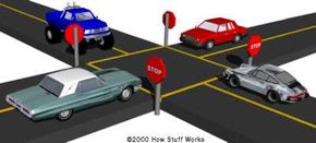
Imagine that each vehicle is a packet of data waiting for an opportunity to continue on its trip.

Think of a hub as a four-way intersection where everyone has to stop. If more than one car reaches the intersection at the same time, they have to wait for their turn to proceed.

Now imagine what this would be like with a dozen or even a hundred roads intersecting at a single point. The amount of waiting and the potential for a collision increases significantly. But wouldn't it be amazing if you could take an exit ramp from any one of those roads to the road of your choosing? That is exactly what a switch does for network traffic. A switch is like a cloverleaf intersection -- each car can take an exit ramp to get to its destination without having to stop and wait for other traffic to go by.

Advertisement

A vital difference between a hub and a switch is that all the nodes connected to a hub share the bandwidth among themselves, while a device connected to a switch port has the full bandwidth all to itself. For example, if 10 nodes are communicating using a hub on a 10-Mbps network, then each node may only get a portion of the 10 Mbps if other nodes on the hub want to communicate as well. But with a switch, each node could possibly communicate at the full 10 Mbps. Think about our road analogy. If all of the traffic is coming to a common intersection, then each car it has to share that intersection with every other car. But a cloverleaf allows all of the traffic to continue at full speed from one road to the next.

Fully Switched Networks

An example of a network using a switch
Image courtesy Cisco Networks

In a fully switched network, switches replace all the hubs of an Ethernet network with a dedicated segment for every node. These segments connect to a switch, which supports multiple dedicated segments (sometimes in the hundreds). Since the only devices on each segment are the switch and the node, the switch picks up every transmission before it reaches another node. The switch then forwards the frame over the appropriate segment. Since any segment contains only a single node, the frame only reaches the intended recipient. This allows many conversations to occur simultaneously on a switched network.

Switching allows a network to maintain full-duplex Ethernet. Before switching, Ethernet was half-duplex, which means that data could be transmitted in only one direction at a time. In a fully switched network, each node communicates only with the switch, not directly with other nodes. Information can travel from node to switch and from switch to node simultaneously.

Advertisement

Fully switched networks employ either twisted-pair or fiber-optic cabling, both of which use separate conductors for sending and receiving data. In this type of environment, Ethernet nodes can forgo the collision detection process and transmit at will, since they are the only potential devices that can access the medium. In other words, traffic flowing in each direction has a lane to itself. This allows nodes to transmit to the switch as the switch transmits to them -- it's a collision-free environment. Transmitting in both directions can effectively double the apparent speed of the network when two nodes are exchanging information. If the speed of the network is 10 Mbps, then each node can transmit simultaneously at 10 Mbps.

Mixed Networks

A mixed network with two switches and three hubs

Most networks are not fully switched because of the costs incurred in replacing all of the hubs with switches.

Instead, a combination of switches and hubs are used to create an efficient yet cost-effective network. For example, a company may have hubs connecting the computers in each department and then a switch connecting all of the department-level hubs.

Advertisement

Routers and Switches

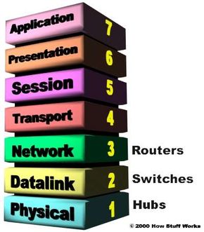
The OSI Reference Model consists of seven layers that build from the wire (Physical) to the software (Application).
HowStuffWorks.com

You can see that a switch has the potential to radically change the way nodes communicate with each other. But you may be wondering what makes it different from a router. Switches usually work at Layer 2 (Data or Datalink) of the OSI Reference Model, using MAC addresses, while routers work at Layer 3 (Network) with Layer 3 addresses (IP, IPX or Appletalk, depending on which Layer 3 protocols are being used). The algorithm that switches use to decide how to forward packets is different from the algorithms used by routers to forward packets.

One of these differences in the algorithms between switches and routers is how broadcasts are handled. On any network, the concept of a broadcast packet is vital to the operability of a network. Whenever a device needs to send out information but doesn't know who it should send it to, it sends out a broadcast. For example, every time a new computer or other device comes on to the network, it sends out a broadcast packet to announce its presence. The other nodes (such as a domain server) can add the computer to their browser list (kind of like an address directory) and communicate directly with that computer from that point on. Broadcasts are used any time a device needs to make an announcement to the rest of the network or is unsure of who the recipient of the information should be.

Advertisement

A hub or a switch will pass along any broadcast packets they receive to all the other segments in the broadcast domain, but a router will not. Think about our four-way intersection again: All of the traffic passed through the intersection no matter where it was going. Now imagine that this intersection is at an international border. To pass through the intersection, you must provide the border guard with the specific address that you are going to. If you don't have a specific destination, then the guard will not let you pass. A router works like this. Without the specific address of another device, it will not let the data packet through. This is a good thing for keeping networks separate from each other, but not so good when you want to talk between different parts of the same network. This is where switches come in.

Packet-switching

LAN switches rely on packet-switching. The switch establishes a connection between two segments just long enough to send the current packet. Incoming packets (part of an Ethernet frame) are saved to a temporary memory area (buffer); the MAC address contained in the frame's header is read and then compared to a list of addresses maintained in the switch's lookup table. In an Ethernet-based LAN, an Ethernet frame contains a normal packet as the payload of the frame, with a special header that includes the MAC address information for the source and destination of the packet.

Packet-based switches use one of three methods for routing traffic:

Advertisement

  • Cut-through
  • Store-and-forward
  • Fragment-free

Cut-through switches read the MAC address as soon as a packet is detected by the switch. After storing the 6 bytes that make up the address information, they immediately begin sending the packet to the destination node, even as the rest of the packet is coming into the switch.

A switch using store-and-forward will save the entire packet to the buffer and check it for CRC errors or other problems before sending. If the packet has an error, it is discarded. Otherwise, the switch looks up the MAC address and sends the packet on to the destination node. Many switches combine the two methods, using cut-through until a certain error level is reached and then changing over to store-and-forward. Very few switches are strictly cut-through, since this provides no error correction.

A less common method is fragment-free. It works like cut-through except that it stores the first 64 bytes of the packet before sending it on. The reason for this is that most errors, and all collisions, occur during the initial 64 bytes of a packet.

Switch Configurations

LAN switches vary in their physical design. Currently, there are three popular configurations in use:

  • Shared memory - This type of switch stores all incoming packets in a common memory buffer shared by all the switch ports (input/output connections), then sends them out via the correct port for the destination node.
  • Matrix - This type of switch has an internal grid with the input ports and the output ports crossing each other. When a packet is detected on an input port, the MAC address is compared to the lookup table to find the appropriate output port. The switch then makes a connection on the grid where these two ports intersect.
  • Bus architecture - Instead of a grid, an internal transmission path (common bus) is shared by all of the ports using TDMA. A switch based on this configuration has a dedicated memory buffer for each port, as well as an ASIC to control the internal bus access.

Advertisement

Transparent Bridging

Most Ethernet LAN switches use a very cool system called transparent bridging to create their address lookup tables. Transparent bridging is a technology that allows a switch to learn everything it needs to know about the location of nodes on the network without the network administrator having to do anything. Transparent bridging has five parts:

  • Learning
  • Flooding
  • Filtering
  • Forwarding
  • Aging

Here's how it works:

Advertisement

In the next section, you'll get a step-by-step description of how transparent bridging works.

Transparent Bridging: The Process

Here's a step-by-step description of transparent bridging:

  • The switch is added to the network, and the various segments are plugged into the switch's ports.
  • A computer (Node A) on the first segment (Segment A) sends data to a computer (Node B) on another segment (Segment C).
  • The switch gets the first packet of data from Node A. It reads the MAC address and saves it to the lookup table for Segment A. The switch now knows where to find Node A anytime a packet is addressed to it. This process is called learning.
  • Since the switch does not know where Node B is, it sends the packet to all of the segments except the one that it arrived on (Segment A). When a switch sends a packet out to all segments to find a specific node, it is called flooding.
  • Node B gets the packet and sends a packet back to Node A in acknowledgement.
  • The packet from Node B arrives at the switch. Now the switch can add the MAC address of Node B to the lookup table for Segment C. Since the switch already knows the address of Node A, it sends the packet directly to it. Because Node A is on a different segment than Node B, the switch must connect the two segments to send the packet. This is known as forwarding.
  • The next packet from Node A to Node B arrives at the switch. The switch now has the address of Node B, too, so it forwards the packet directly to Node B.
  • Node C sends information to the switch for Node A. The switch looks at the MAC address for Node C and adds it to the lookup table for Segment A. The switch already has the address for Node A and determines that both nodes are on the same segment, so it does not need to connect Segment A to another segment for the data to travel from Node C to Node A. Therefore, the switch will ignore packets traveling between nodes on the same segment. This is filtering.
  • Learning and flooding continue as the switch adds nodes to the lookup tables. Most switches have plenty of memory in a switch for maintaining the lookup tables; but to optimize the use of this memory, they still remove older information so that the switch doesn't waste time searching through stale addresses. To do this, switches use a technique called aging. Basically, when an entry is added to the lookup table for a node, it is given a timestamp. Each time a packet is received from a node, the timestamp is updated. The switch has a user-configurable timer that erases the entry after a certain amount of time with no activity from that node. This frees up valuable memory resources for other entries. As you can see, transparent bridging is a great and essentially maintenance-free way to add and manage all the information a switch needs to do its job!

In our example, two nodes share segment A, while the switch creates independent segments for Node B and Node D. In an ideal LAN-switched network, every node would have its own segment. This would eliminate the possibility of collisions and also the need for filtering.

Advertisement

Redundancy

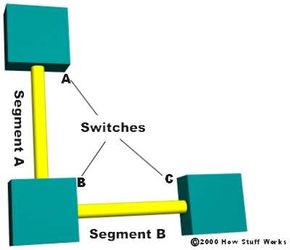
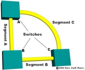
When we talked about bus and ring networks earlier, one issue was the possibility of a single point of failure. In a star or star-bus network, the point with the most potential for bringing all or part of the network down is the switch or hub. Look at the example below:

In this example, if either switch A or C fails, then the nodes connected to that particular switch are affected, but nodes at the other two switches can still communicate. However, if switch B fails, then the entire network is brought down. What if we add another segment to our network connecting switches A and C?

Advertisement

In this case, even if one of the switches fails, the network will continue. This provides redundancy, effectively eliminating the single point of failure.

But now we have a new problem.

Broadcast Storms

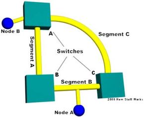
In the last section, you discovered how switches learn where the nodes are located. With all of the switches now connected in a loop, a packet from a node could quite possibly come to a switch from two different segments. For example, imagine that Node B is connected to Switch A, and needs to communicate with Node A on Segment B. Switch A does not know who Node A is, so it floods the packet.

The packet travels via Segment A or Segment C to the other two switches (B and C). Switch B will add Node B to the lookup table it maintains for Segment A, while Switch C will add it to the lookup table for Segment C. If neither switch has learned the address for Node A yet, they will flood Segment B looking for Node A. Each switch will take the packet sent by the other switch and flood it back out again immediately, since they still don't know who Node A is. Switch A will receive the packet from each segment and flood it back out on the other segment. This causes a broadcast storm as the packets are broadcast, received and rebroadcast by each switch, resulting in potentially severe network congestion.

Advertisement

Which brings us to spanning trees...

Spanning Trees

To prevent broadcast storms and other unwanted side effects of looping, Digital Equipment Corporation created the spanning-tree protocol (STP), which has been standardized as the 802.1d specification by the Institute of Electrical and Electronic Engineers (IEEE). Essentially, a spanning tree uses the spanning-tree algorithm (STA), which senses that the switch has more than one way to communicate with a node, determines which way is best and blocks out the other path(s). The cool thing is that it keeps track of the other path(s), just in case the primary path is unavailable.

Here's how STP works:

Advertisement

Each switch is assigned a group of IDs, one for the switch itself and one for each port on the switch. The switch's identifier, called the bridge ID (BID), is 8 bytes long and contains a bridge priority (2 bytes) along with one of the switch's MAC addresses (6 bytes). Each port ID is 16 bits long with two parts: a 6-bit priority setting and a 10-bit port number.

A path cost value is given to each port. The cost is typically based on a guideline established as part of 802.1d. According to the original specification, cost is 1,000 Mbps (1 gigabit per second) divided by the bandwidth of the segment connected to the port. Therefore, a 10 Mbps connection would have a cost of (1,000/10) 100.

To compensate for the speed of networks increasing beyond the gigabit range, the standard cost has been slightly modified. The new cost values are:

Bandwidth 4 Mbps = 250 STP Cost Value

Bandwidth 10 Mbps = 100 STP Cost Value

Bandwidth 16 Mbps = 62 STP Cost Value

Bandwidth 45 Mbps = 39 STP Cost Value

Bandwidth 100 Mbps = 19 STP Cost Value

Bandwidth 155 Mbps = 14 STP Cost Value

Bandwidth 622 Mbps = 6 STP Cost Value

Bandwidth 1 Gbps = 4 STP Cost Value

Bandwidth 10 Gbps = 2 STP Cost Value

You should also note that the path cost can be an arbitrary value assigned by the network administrator, instead of one of the standard cost values. Each switch begins a discovery process to choose which network paths it should use for each segment. This information is shared between all the switches by way of special network frames called bridge protocol data units (BPDU). The parts of a BPDU are:

  • Root BID - This is the BID of the current root bridge.
  • Path cost to root bridge - This determines how far away the root bridge is. For example, if the data has to travel over three 100-Mbps segments to reach the root bridge, then the cost is (19 + 19 + 0) 38. The segment attached to the root bridge will normally have a path cost of zero.
  • Sender BID - This is the BID of the switch that sends the BPDU.
  • Port ID - This is the actual port on the switch that the BPDU was sent from.
  • All of the switches are constantly sending BPDUs to each other, trying to determine the best path between various segments. When a switch receives a BPDU (from another switch) that is better than the one it is broadcasting for the same segment, it will stop broadcasting its BPDU out that segment. Instead, it will store the other switch's BPDU for reference and for broadcasting out to inferior segments, such as those that are farther away from the root bridge.
  • A root bridge is chosen based on the results of the BPDU process between the switches. Initially, every switch considers itself the root bridge. When a switch first powers up on the network, it sends out a BPDU with its own BID as the root BID. When the other switches receive the BPDU, they compare the BID to the one they already have stored as the root BID. If the new root BID has a lower value, they replace the saved one. But if the saved root BID is lower, a BPDU is sent to the new switch with this BID as the root BID. When the new switch receives the BPDU, it realizes that it is not the root bridge and replaces the root BID in its table with the one it just received. The result is that the switch that has the lowest BID is elected by the other switches as the root bridge.
  • Based on the location of the root bridge, the other switches determine which of their ports has the lowest path cost to the root bridge. These ports are called root ports, and each switch (other than the current root bridge) must have one.
  • The switches determine who will have designated ports. A designated port is the connection used to send and receive packets on a specific segment. By having only one designated port per segment, all looping issues are resolved! Designated ports are selected based on the lowest path cost to the root bridge for a segment. Since the root bridge will have a path cost of "0," any ports on it that are connected to segments will become designated ports. For the other switches, the path cost is compared for a given segment. If one port is determined to have a lower path cost, it becomes the designated port for that segment. If two or more ports have the same path cost, then the switch with the lowest BID is chosen.
  • Once the designated port for a network segment has been chosen, any other ports that connect to that segment become non-designated ports. They block network traffic from taking that path so it can only access that segment through the designated port.

Each switch has a table of BPDUs that it continually updates. The network is now configured as a single spanning tree, with the root bridge as the trunk and all the other switches as branches. Each switch communicates with the root bridge through the root ports, and with each segment through the designated ports, thereby maintaining a loop-free network. In the event that the root bridge begins to fail or have network problems, STP allows the other switches to immediately reconfigure the network with another switch acting as root bridge. This amazing process gives a company the ability to have a complex network that is fault-tolerant and yet fairly easy to maintain.
Routers and Layer 3 Switching

Layer 3 switches actually work at the Network layer.
HowStuffWorks.com

While most switches operate at the Data layer (Layer 2) of the OSI Reference Model, some incorporate features of a router and operate at the Network layer (Layer 3) as well. In fact, a Layer 3 switch is incredibly similar to a router.

When a router receives a packet, it looks at the Layer 3 source and destination addresses to determine the path the packet should take. A standard switch relies on the MAC addresses to determine the source and destination of a packet, which is Layer 2 (Data) networking.

Advertisement

The fundamental difference between a router and a Layer 3 switch is that Layer 3 switches have optimized hardware to pass data as fast as Layer 2 switches, yet they make decisions on how to transmit traffic at Layer 3, just like a router. Within the LAN environment, a Layer 3 switch is usually faster than a router because it is built on switching hardware. In fact, many of Cisco's Layer 3 switches are actually routers that operate faster because they are built on "switching" hardware with customized chips inside the box.

The pattern matching and caching on Layer 3 switches is similar to the pattern matching and caching on a router. Both use a routing protocol and routing table to determine the best path. However, a Layer 3 switch has the ability to reprogram the hardware dynamically with the current Layer 3 routing information. This is what allows for faster packet processing.

On current Layer 3 switches, the information received from the routing protocols is used to update the hardware caching tables.

VLANs

As networks have grown in size and complexity, many companies have turned to virtual local area networks (VLANs) to provide some way of structuring this growth logically. Basically, a VLAN is a collection of nodes that are grouped together in a single broadcast domain that is based on something other than physical location.

You learned about broadcasts earlier, and how a router does not pass along broadcasts. A broadcast domain is a network (or portion of a network) that will receive a broadcast packet from any node located within that network. In a typical network, everything on the same side of the router is all part of the same broadcast domain. A switch that you have implemented VLANs on has multiple broadcast domains, similar to a router. But you still need a router (or Layer 3 routing engine) to route from one VLAN to another -- the switch can't do this by itself.

Advertisement

Here are some common reasons why a company might have VLANs:

  • Security - Separating systems that have sensitive data from the rest of the network decreases the chances that people will gain access to information they are not authorized to see.
  • Projects/Special applications - Managing a project or working with a specialized application can be simplified by the use of a VLAN that brings all of the required nodes together.
  • Performance/Bandwidth - Careful monitoring of network use allows the network administrator to create VLANs that reduce the number of router hops and increase the apparent bandwidth for network users.
  • Broadcasts/Traffic flow - Since a principle element of a VLAN is the fact that it does not pass broadcast traffic to nodes that are not part of the VLAN, it automatically reduces broadcasts. Access lists provide the network administrator with a way to control who sees what network traffic. An access list is a table the network administrator creates that lists which addresses have access to that network.
  • Departments/Specific job types - Companies may want VLANs set up for departments that are heavy network users (such as multimedia or engineering), or a VLAN across departments that is dedicated to specific types of employees (such as managers or sales people).

You can create a VLAN using most switches simply by logging into the switch via Telnet and entering the parameters for the VLAN (name, domain and port assignments). After you have created the VLAN, any network segments connected to the assigned ports will become part of that VLAN.

While you can have more than one VLAN on a switch, they cannot communicate directly with one another on that switch. If they could, it would defeat the purpose of having a VLAN, which is to isolate a part of the network. Communication between VLANs requires the use of a router.

VLANs can span multiple switches, and you can have more than one VLAN on each switch. For multiple VLANs on multiple switches to be able to communicate via a single link between the switches, you must use a process called trunking -- trunking is the technology that allows information from multiple VLANs to be carried over a single link between switches.

On the next page, you'll learn about trunking.

VLAN Trunking Protocol

The VLAN trunking protocol (VTP) is the protocol that switches use to communicate among themselves about VLAN configuration.

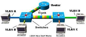
In the image above, each switch has two VLANs. On the first switch, VLAN A and VLAN B are sent through a single port (trunked) to the router and through another port to the second switch. VLAN C and VLAN D are trunked from the second switch to the first switch, and through the first switch to the router. This trunk can carry traffic from all four VLANs. The trunk link from the first switch to the router can also carry all four VLANs. In fact, this one connection to the router allows the router to appear on all four VLANs, as if it had four different physical ports connected to the switch.

Advertisement

The VLANs can communicate with each other via the trunking connection between the two switches using the router. For example, data from a computer on VLAN A that needs to get to a computer on VLAN B (or VLAN C or VLAN D) must travel from the switch to the router and back again to the switch. Because of the transparent bridging algorithm and trunking, both PCs and the router think that they are on the same physical segment!

As you can see, LAN switches are an amazing technology that can really make a difference in the speed and quality of a network.

For more information on LAN switches, networks and related topics, check out the links on the next page.